Fair Shine industrial (Hong Kong) Co., Limited
To provide customers with the most comprehensive precision mold parts solutions.

Automotive Mold Parts | |
Product Name | Automotive Mold Parts |
Brand Name | Fair Shine |
Place of Origin | Dongguan, Guangdong, China |
Specification | Customized on Request |
Customization | Material, size, shape, convex and concave marking, coating, laser engraving mark and packing are all customizable. |
Product Material | Carbide.ASP23 Vanadis.CPMRTXM4.SKD11SKD61HSSA2M2D2SUJ2.S45C.ect |
Standard | DIN ANSI BS JIS |
Tolerance | ±0.002mm |
Surface Treatment | TiCNTiN,Aitain,Ticrnnitriding Black oxygened Black coating etc available |
Polishness | Close to Ra0.2 Hardness Depends on material(HRC60~94) |
Hardness | Depends on material(HRC60~94) |
Shaping Mode | Grinding, wire cutting, EDM, cnc machining, cnc turning, cnc Milling |
Application | Machinery Parts and Molds |
Dongguan Huixiang Mold Technology Co., Ltd. is located in Dongcheng District, Dongguan City, the economic window of China's heavy industry. It is a company integrating R&D, manufacturing, sales and service, and is one of the OEM processing manufacturers of many domestic and foreign mold parts peers.
Huixiang's technical backbones all have decades of experience in processing mold parts from Japan and Taiwan, and they conduct various skills training and level assessments from time to time, laying a solid foundation for the company's sustainable development in the mold parts manufacturing industry. To move towards industry standardization and modernization. The company has always strictly followed the technical standards for production and inspection of international manufacturers in Europe, Japan and the United States. It can also design and provide various standard and non-standard mold accessories according to the different requirements of customers. The main products include mold accessories, inserts, inclined top seats, pen model cores, bottle cap cores, mold core sleeves, slingshots, punch needles, punches, thimbles, cylinders, flat thimbles, auxiliaries, self-lubricating (without Oil supply) block, guide sleeve, guide post, outer guide post Assembly, tooling fixture, FA automation parts, clamping buckle (clamp) reset mechanism, date stamp, etc. Various non-standard parts can be customized.
Huixiang's products are widely used in major industries such as hardware, plastics, die-casting, cosmetics, spray pumps, electronic appliances, electromechanical, stationery, medical equipment, semiconductors, etc. The products are sold in major cities across the country and exported to Southeast Asia, Europe, the United States, and the Middle East. and other areas.
We have always adhered to the business philosophy of "reliable quality, technological innovation, harmonious development, and sustainable management" to give you "better prices, on-time delivery and perfect quality." We look forward to sincere cooperation with you and create a better future together!
1. Pen making/cosmetics/packaging products: pen model refills/pen cap accessories/pen refill thread inserts/lipstick series/spray molds;
2. Medical packaging equipment products: syringe core/syringe core (combination (pieces)/test tube core/medical packaging bottle cap screw core/drawing cover core and push plate cover; front and rear mold cores such as upper and lower caps of mascara;
3. Optoelectronic/digital electronic products: precision optoelectronic shaft/precision insert Sub/core/busting/precision positioning, etc., the accuracy tolerance is generally controlled within 0.002-0.005, all with test reports for customer inspection;
4. Home appliances, automotive machinery products: self-lubricating wear-resistant blocks (high-strength brass Add graphite)/No oil self-lubricating guide bushing, movable core Assembly (inclined top seat)/guide column assistant/positioning column, etc.;
5. Bushings, die inserts, lower molds, CNC Customized standard and non-standard precision stamping mold accessories such as concave molds, special-shaped bushings, contour sleeves, floating pins, cross pin floating pins, guide lifting pins, tungsten steel punches, etc.;
6. Non-standard customization of SKH51 thimbles, SKD61 thimbles, supporting pins, flat thimbles, shooting pins, cylinder pins, push tubes, imported material thimbles and cylinder cylinders;
7 . Guide post guide bushing, GP auxiliary guide post, GP auxiliary guide bushing, SRP ball guide post guide bush, SGP sliding guide post guide bush, discharge plate guide post guide bush, TRP detachable guide post guide bush, independent guide post , non-standard guide posts and bushings and other cold stamping mold accessories;
8. Drilling die sets, beryllium bronze molds, diamond pins, positioning pins, countersunk hole pins, ejection pins, pins, connecting screws, material blocking shafts, blocking Customized mechanical parts such as material sleeves and bushings;
What should we pay attention to when designing and processing automotive injection molds?
1.1 Plastic product design is the key
Plastic product design is a key stage in the design of automotive injection molds. For the design of plastic products, it is necessary to simplify the plastic product model as much as possible. Simplified design is a clearly stated requirement for each optimization stage of plastic products.
On the basis of this provision, important basic requirements should be considered. For example, in the thickness design of automobile injection molds, try to make the thickness of the mold as uniform as possible to avoid inaccuracies. Appropriate uneven glue position appears.
1.2 Basic requirements for parts of a molding mold
Certain standards should be met in terms of compressive strength and strength, otherwise it will not be able to withstand friction and will affect the construction quality. The strength requirement cannot be less than HRC35 at least. A few special requirements require a strength of 50 to 52HRC or above. Plastic products are To make the surface glossy after forming, it can be done by grinding and polishing.
1.3 Select the parting line and parting surface of the automotive injection mold
The way to determine the parting line can be determined based on the shape of the part. The function of the fractal line is just to divide the product into two parts, and the boundary lines also exist. It is divided into two parts: the fixed mold is formed, and the movable mold is the other part. To obtain the parting surface of the automotive injection mold, you can use fractal lines. Use fractal lines to scan around the mold at multiple locations to determine the parting surface of the mold.
1.4 Frequently Asked Questions about Parting Surface Design Scheme
One thing that must be paid attention to in the parting surface of automobile injection molds is to ensure that there is a sealing distance between each inclined surface. At the same time, the effectiveness of the distance must be ensured, so that the plastic melt will not be easily lost during the injection process. The name sealing distance is due to this function, which can seal the material. In the process of establishing parting surfaces, if you encounter parting surfaces with large height differences such as slopes or slopes and steps, whether it is one or several, you must set a standard plan for them, which will be beneficial. Production processing and measurement.
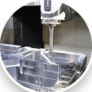



Common mold problems and solutions
1. Waste material jumping hole
a. The length of the punch is not enough. Press the punch edge to cut into the die and add 1 mm to the material thickness to replace the punch.
b. The die gap is too large. Cut the tool to reduce the gap or use a coating machine to reduce the gap.
c. The punch or template has not been demagnetized. Use a demagnetizer to demagnetize the punch or template.
2. Waste material blocks the hole
a. The blanking hole is small or the blanking hole is offset and the blanking hole is enlarged to make the blanking smooth.
b. The blanking hole has chamfering. Enlarge the blanking hole and remove the chamfering.
c. If there is no taper on the knife edge, cut the taper or expand the hole on the back to reduce the length of the straight wall.
d. The straight wall of the knife edge is too long and drilled on the opposite side to shorten the straight wall of the knife edge.
e. The cutting edge collapses, resulting in a large blade, and the cutting edge needs to be blocked and re-grinded.
3. Poor cloak
a. The cutting edge collapses, causing the blade to be too large and the cutting edge needs to be ground again.
b. If the gap between the punch and the die is too large, the line will cut into the block and the gap must be re-adjusted.
c. The concave mold blade has poor finish and the polished blade has a straight wall position.
d. The gap between the punch and the die is too small. Save the mold again and adjust the gap.
e. The ejection force is too large. Pull out the cape in the opposite direction and replace the spring to reduce the ejection force.
4. Uneven trimming
a. Positioning offset adjustment positioning
b. With single-sided forming, pull the material to increase the pressing force and adjust the positioning
c. Design error, resulting in uneven knife connection and re-cutting the cutting edge insert.
d. Feeding is not allowed to adjust the feeder
e. If the feeding step distance is calculated incorrectly, recalculate the step distance and reset the tool receiving position.
5. The punch is easy to break
a. The closing height is too low and the punch cutting edge is too long. Adjust the closing height.
b. Improper positioning of the material, causing the punch to cut off one side, adjusting the positioning or the feeding device to break due to uneven stress.
c. The lower die waste blocks the knife edge, causing the punch to break and drill a large blanking hole to make the blanking smooth.
d. The fixed part of the punch (clamp) and the guide part are repaired or re-cut into blocks to make the punch move smoothly up and down (plate-making).
e. The plate-making guide is poor, causing the punch to be stressed on one side. Re-adjust the plate-making gap.
f. The punch blade is too short and interferes with the plate making. Replace the punch and increase the length of the blade.
g. The punch is not fixed well and it moves up and down. Re-fix the punch so that it cannot move up and down.
h. The punch edge is not sharp and re-grind the edge.
I. The surface of the punch is strained and the force is uneven during stripping. Replace the punch.
j. The punch is too thin, too long, and not strong enough. Re-change the punch type.
k. The punch hardness is too high and the punch material is wrong. Replace the punch material and adjust the heat treatment hardness.
6.Iron filings
a. Pressure bar misalignment and recalculate the pressure bar position or bending position
b. The bending gap is too small. Extrude iron chips to readjust the gap, or grind the forming block or grinding forming punch.
c. The bending punch is too sharp and trims the R corner
d. There is too little material to connect the knife edge and reconnect the knife edge.
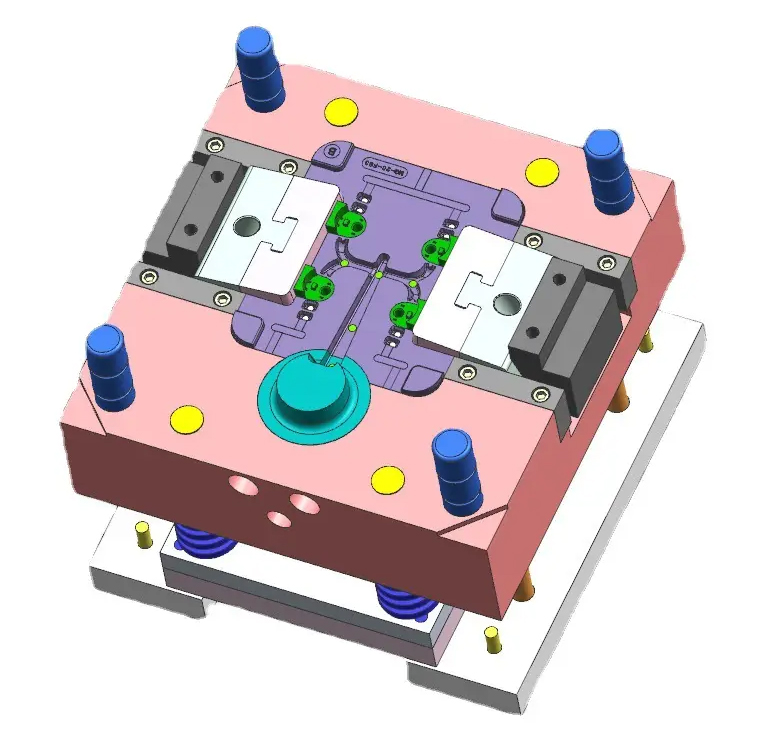
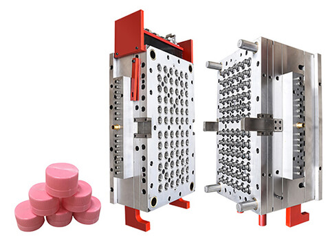
Polishing of molded surfaces
Why does the molding surface need to be polished in the injection mold factory? The roughness of the molding surface directly affects the surface roughness of the plastic part. Due to the increasingly wide range of uses of plastic parts, customers' requirements for the surface quality of plastic parts continue to increase. The molding surface obtained by ordinary mechanical processing and electrical processing often meets the requirements of fullness. Therefore, the molding surface must be processed after injection mold processing or electrical processing. Processed to improve surface roughness. Polishing includes ordinary polishing and mirror polishing. The roughness Ra of ordinary polishing can reach 0.2m, and the roughness Ra of mirror polishing can reach 0.008μm. Energy surface polishing is mainly used for the injection molding surface of transparent plastic parts.
The polished molding surface also has the following advantages.
① During injection molding production, plastic parts are easier to demould.
② It can reduce the wear of plastic melt on mold production.
③It can reduce the flow resistance of plastic melt.
④It can reduce mold production breakage or bursting caused by temporary excessive load or fatigue.
How to judge the surface quality of mold production and molding? When judging the surface quality of injection molds, you should pay attention to the following points:
① The mold surface must have a geometrically correct plane without any protrusions on the surface.
② When the mold molding surface is mirror polished, the surface roughness is usually judged by the naked eye, and it is often difficult to judge by the naked eye, because a surface that is judged smooth by the naked eye may not be a completely smooth plane in the true sense of geometry.
③The surface of the mold must be completely free of scratches, such as small blisters and local peeling left by carbonized particles being pulled out. If the injection mold processing quality requirements are strict, the smoothness of the molding surface can be measured using special instruments, such as light wave refraction or a magnifying glass.
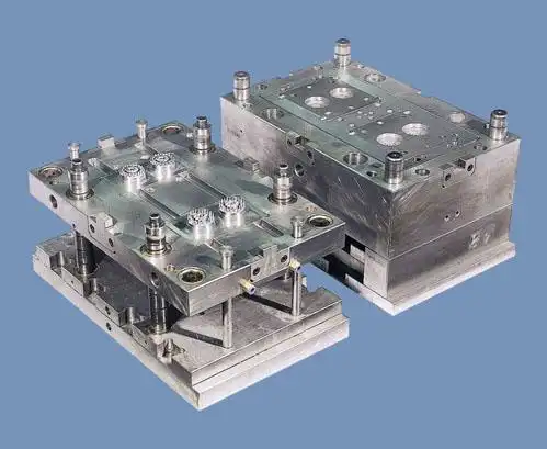
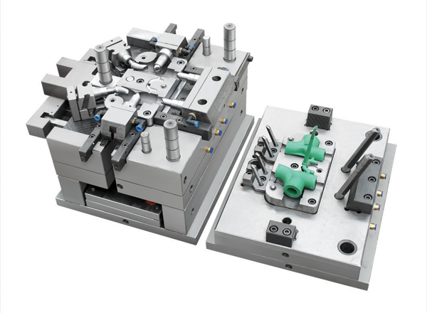
(1) Polishing process and skills Polishing process and skills are very important. If the skills are used properly, the effect will be very good. On the contrary, if the skills are poor, not only will the roughness of the molded surface not be reduced, but the original surface quality will be damaged. Make the molding surface rougher. First of all, engraving injection molds are mostly processed by milling machines, EDM machines or precision castings. If the mold surface is required to be smooth, the milled surface must undergo rough grinding, fine grinding and polishing. The surface processed by the electrode only needs to be finely ground and polished, while the precision casting mold only needs to be polished with diamond paste. Quick and good polishing can be done with a grinding wheel, first grinding away the knife marks left by machining. Whether you are polishing mechanically or manually, please abide by the following principles:
① A large amount of coolant should be used when grinding the grinding wheel to avoid overheating, which will affect the processing hardness of the injection mold and cause local annealing of the molding surface.
② A clean and scratch-free grinding wheel or grinding stone should be used. For steel with higher hardness, a softer grinding stone should be used.
③Every time a finer grinding wheel is used, the workpiece and the palm of the hand must be thoroughly cleaned to avoid leaving coarse sand particles and scratching the molding surface. The finer the grinding wheel, the more attention should be paid to it.
④When using a finer first-level grinding wheel each time, the direction of the injection mold should be changed to 45° from the previous time, and then grinded. When the new grinding pattern completely covers the direction of the previous grinding pattern, continue grinding for 25% more time to deform a thin surface layer, and then use a finer grinding wheel.
⑤The advantage of constantly changing the direction of stone grinding is that it can avoid irregular patterns.
⑥When grinding large flat injection molds, you should try to avoid using soft hand-held grinding discs and use grinding stones to avoid irregular patterns.
(2) Polishing precautions
① Before trying out the mold, you must check whether the polishing fully meets the requirements or whether it is completely completed.
② Whether the spark pattern is correct and whether it can be demoulded.
③For all mirror polishing, the steel must be ASSAB136 or NAK80, with a hardness of 52~54HRC.
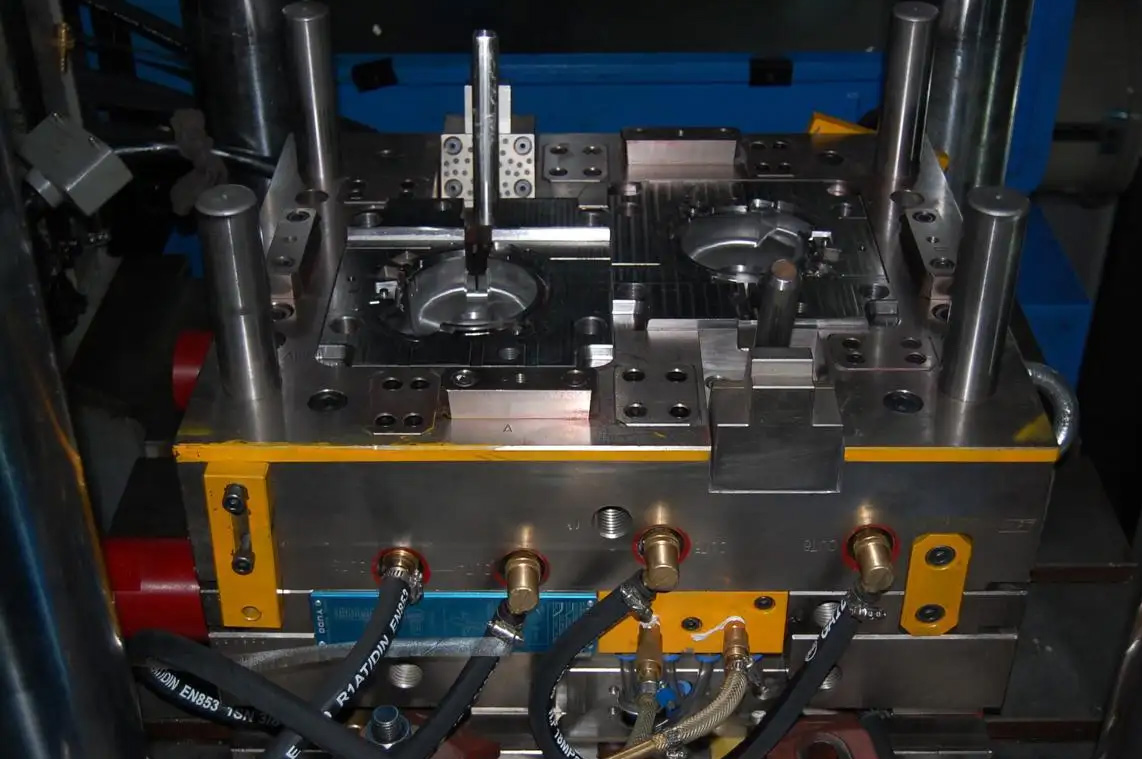
01. Assembly of internal mold inserts
(1) Type A does not have a pass-through, is embedded, and is fastened with screws. The internal mold inserts include fixed mold inserts and movable mold inserts. The inserts of the A-type assembly method do not have a pass-through. They are fixed by screws respectively. Fixed mold plate A and movable mold plate B. Number and size of fastening screws Screw assembly dimensions,
(2) The B-type insert is inserted and tightened with screws. The holes for fixing the inner mold inserts in plates A and B are made into through holes, commonly known as inserts. At this time, the inserts are fixed on the fixed mold panel and the movable mold support plate respectively by screws. The number, size and assembly dimensions of the screws are the same as type A. .
(3) C-shaped circular insert with fixed steps,
(4) D-type circular insert, fixed with "ten steps of pressure plate",
(5) Type E adds two wedge blocks on the basis of type A. This assembly method is mainly used in large mold bases (mold base width ≥ 400mm) and insert size ≥ 200mmx200mm. The purpose is to facilitate internal mold inserts. Assembly and disassembly, and ensuring the positioning requirements of inserts and mold bases. Insert wedge block size. Material: 45 steel, heat treatment: quenched to 42~46HRC.
The design points of the inner mold insert wedge block are as follows.
① Both the moving and fixed molds must be equipped with wedge blocks, which should be installed on the two opposite sides of the datum plane.
②There should be no gap between the template and the wedge block
③ Mark the corresponding positions of the wedge block and template to prevent installation errors.
④Assemble and remove the screws locking the wedge block from the parting surface.
⑤ There should be a screw hole on the front of the wedge block to facilitate the removal of the wedge block.
02. Assembly of the core
(1) F-type steps are fixed,
(2) G-type screw fastening,
(3) The H-shaped step is fixed and the round pin prevents rotation. In the design, if the diameter of the circular insert is<40mm, the="" step="" height="" must="" be="" greater="" than="" 5mm="">
(4) The mold core is set through and tightened with screws.
(5) The T-shaped molding part is large and the fixed part is small, commonly known as mushroom insert.
(6) The K-type insert is set through, and the hook is used to replace the step for positioning.

Fair Shine industrial (Hong Kong) Co., Limited
To provide customers with the most comprehensive precision mold parts solutions.
+86 189 2682 6341
Block 1, No. 12, Wusong 4th Street, Yuwu Industrial Zone, Dongcheng District, Dongguan, Guangdong, China
Copyright © 2025 Dongguan Huixiang Mold Technology Co., Ltd all rights reservrd.
Technical support: HuaShang